The process of layer-by-layer freezing of ice
I would like to share the results of the work done on the preparation of a term paper on the automation of technological ice production
Probably useful to those who study automation or who have a similar task.
Task definition:
It is necessary to develop a control system based on the OWEN PLC160 equipment with verification of the elements of technological equipment. Rework the electrical control circuit into software control sequences in the Codesys v2.3 program. Make screen forms with the possibility of remote control.
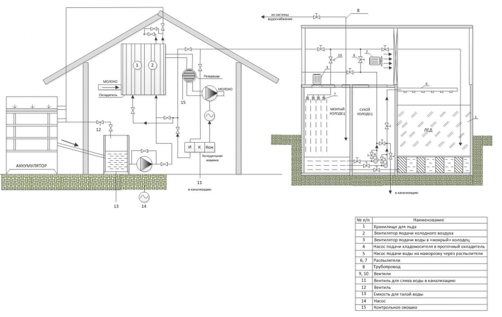
The technological scheme of the ice accumulator is presented on the graphic sheet (functional diagram).
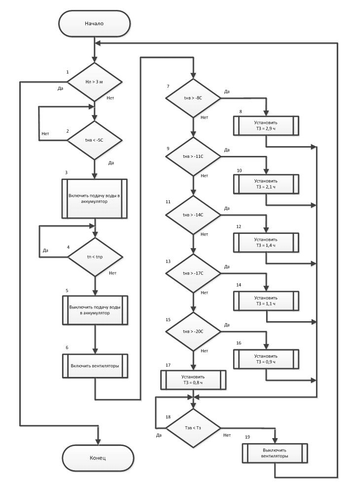
Below is a diagram of the algorithm for controlling the process of layer-by-layer freezing of ice, taking into account the dependence of the freezing time of the water layer on the outside air temperature.
Description of the algorithm:
Start.
1. If the thickness of the accumulated ice layer is Hl ˃ 3m, then the algorithm ends; otherwise, go to step 2.
2. If the outdoor air temperature tnv ˂ -5 ̊С, then the algorithm is suspended, otherwise, go to step 3.
3. Turn on the water supply to the battery. Estimated water supply time Tpr.
Tpr=(L*b*h)/Q,
Where L – ice storage tank length, m;
b – tank width, m;
h – water layer thickness, m;
Q – hearth supply, m3/s.
4. If the water supply time is Tp ˂ Tpr, then go to step 4 of the algorithm, otherwise go to step 5.
5. Turn off the water supply to the battery.
6. Turn on fans.
7. If the outdoor air temperature is tн ˃ -8 ̊С, then go to step 8 of the algorithm, otherwise go to step 9.
8. Set the freezing time of the water layer Tz = 2.9 hours.
9. If the outdoor air temperature tnv ≥ -11 ̊С, then go to step 10 of the algorithm, otherwise go to step 11.
10. Set the freezing time of the water layer Tz = 2.1 hours.
11. If the outdoor temperature is tnv ˃ -14 ̊С, then go to step 12 of the algorithm, otherwise go to step 13.
12. Set the freezing time of the water layer Tz = 1.4 hours.
13. Set the freezing time of the water layer Tz = 1.4 hours.
14. Установить время замерзания слоя воды Tз = 1,1 часа.
15. Если температура наружного воздуха tнв ˃ -20 ̊С, то перейти к п. 16 алгоритма, в противном случае перейти к п. 17.
16. Set the freezing time of the water layer Tz = 0.9 hours.
17. Set the freezing time of the water layer Tz = 0.8 hours.
18. If the freezing time of water Tw ˂ Tw, then go to step 18 of the algorithm, otherwise go to step 19.
19. Turn off fans. Go to step 1 of the algorithm.
Development of circuit diagrams for the control system of an automated ice accumulator.
The process control system consists of several low-voltage complete devices (LVD) that provide process control in manual and automatic modes, and the processes in the ice accumulator are controlled by NKU-3 and NKU-4.
NKU-4, which controls the processes of maintaining the water level in the "wet" well and heating the "dry" well (ensuring a positive temperature in the well), it is advisable to place it in an ice accumulator. In this case, the cable lines from the cabinet to the level sensor, temperature sensor and electric heater will be of the minimum length.
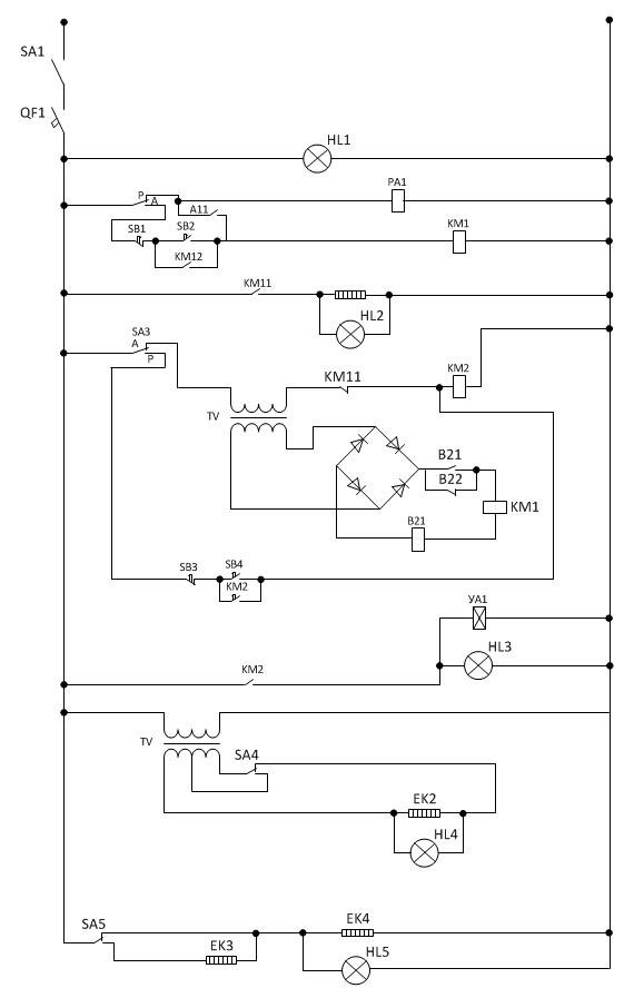
The electrical circuit diagram of the NKU-4 is shown in the drawing.

The control cabinet is connected to the 220V AC mains through the SA1 package switch and the QF1 circuit breaker, which protects the line from short circuits. The HL1 lamp signals the supply of voltage to the circuit.
The choice of the well heating mode (manual or automatic) is carried out by the package switch SA2. In automatic mode, the temperature controller PA1 receives power. The temperature sensor RK is installed in the "dry" well of the ice accumulator. If the air temperature in the well is below the A1 regulator setting, the A1.1 regulator contacts turn on the KM1 magnetic starter, which turns on the EK1 electric heater with its KM1.1 contacts. The HL2 lamp signals the supply of voltage to EK1. When the air temperature in the well reaches the setpoint of the A1 regulator, the heating is turned off.
The choice of the mode of water supply to the "wet" well (manual or automatic) is carried out by the package switch SA3. In automatic mode, the switching on of the solenoid valve is controlled by the contacts of the relay KV1. Relay KV1 is connected in series with the electrodes of the contact water level sensor located in the "wet" well.
Primary water level transducers are electrodes isolated from each other, installed at a certain level. Relay KV1 is powered by DC voltage obtained using diodes VD1 ... VD4, and for safety reasons, voltage is supplied to the electrodes from a step-down transformer TV1.
When the water closes the electrodes of the upper level sensor B2.1 (H), the KV1 relay is also powered by its break contacts
KV1.1 turns on the YA1 valve, the water supply to the well stops. Relay KV1 loses power if the water level in the well is below the low level electrodes B2.2 (L). In this case, the contacts KV1.1 are closed, the YA1 valve is turned off, water is supplied to the well.
The HL3 lamp signals the voltage supply to YA1.
In the cold season, the level sensor may freeze and, as a result, its performance may be impaired. Therefore, heating of the level sensor is provided, using an electric heater EK2, located in the central electrode of the sensor.
The activation of the sensor heating and the stepwise regulation of the heating is carried out using the package switch SA4. The HL4 lamp signals the activation of the heating of the level sensor. To prevent the formation of condensate on the inner walls of the control cabinet, an internal heating of the cabinet is provided, which is switched on by the SA5 switch. The degree of heating is adjustable. You can turn on the heating element EK3 or EK4 and EK5 connected in series. The lamp HL5 signals the inclusion of cabinet heating.
NKU-3 controls the processes of layer-by-layer freezing of ice in the ice accumulator, the supply of coolant to the cooler from the under-ice space and controls the operation of the fans.
The automation system for layer-by-layer ice freezing is simplified if the moment of ice formation is determined using a special sensor. The moment of ice formation can be determined by the change in the mechanical, electrical, optical or other parameters of the medium during the phase transition of water to ice.
The problem of creating an ice formation sensor is rather complicated due to the fact that the controlled layer moves during the freezing process. Therefore, the sensor must either move simultaneously with the growth of the ice mass, or be distributed, multipoint.
A promising direction is the development of a sensor based on the difference in the electrical conductivity of ice and water. The resistance of ice is greater than the resistance of water by 500 times or more. This means that it is possible to create a sensor based on this principle. The sensor consists of an electrical part located in the ice mass and an electronic part used to analyze the resistance of the medium and issue a relay control signal to the control system of the frost water supply pump at the time of ice formation. This sensor has a number of disadvantages. False alarms of the sensor occur due to freezing of metal electrodes, when the bulk of the water has not yet frozen. Therefore, it is necessary to refine the sensor, aimed at providing
automatic setpoint change as ice builds up.
The graphic sheet shows the electrical circuit diagram of NKU-3, developed taking into account the dependence of the freezing time of the water layer on the outside air temperature.
The control cabinet is connected to the three-phase AC 380/220V circuit through the QF1 circuit breaker, which protects the line from short circuits. The HL1 lamp signals the supply of voltage. Power is supplied to the NKU-4 through the automatic switch QF2. The HL2 lamp signals the supply of power to the NKU-4, the NKU-3 controls the electric motors: M, M2 and M3 - fans 1, 2 and 3; M4 - frost pump; M5 - cooling pump. Control is carried out using magnetic starters KM1 ... KM5. All electric motors are protected from overloads by thermal relays KK1…KK5. The choice of the freezing mode (manual or automatic) is carried out by the packet switch SA1. In the "manual" mode, the switching on and off of the electric motors of the M1, M2, M3 fans is controlled by the SB2 "start" and SB1 "stop" buttons.
The required number of working fans is set by switches SA2, SA3, SA4.
The electric motor M4 of the frost pump is controlled by the buttons SB4 "start" and SB3 "stop". Signaling about the voltage supply to the electric motors of the fans and the frost pump is carried out by HL3 ... HL6.
In the automatic freezing mode, the sensors are powered - temperature relays A1, A2 and time relay KT2, which form pauses between water supplies for freezing, depending on the ambient temperature. The magnetic starter KM4, which includes the electric motor of the water supply pump for freezing, and the time relay KT1, connected in parallel, which determines the duration of the water supply for freezing, are powered through the corresponding series-connected contacts of the temperature relay and the time relay. After working out the required duration of water supply for freezing, relay KT1 with its contacts KT1.1 returns the circuit to its original state. Using the switch SA5, you can set the mode of constant switching on of the fans, regardless of the operation of the water supply pump for freezing.
The coolant supply pump for milk cooling is switched on using the SB7 (SB8) “start” buttons and the buttons are turned off
SB5 (SB6) "stop". The HL7 lamp signals the supply of voltage to the cooling pump motor.
What was created:
1. A control algorithm was created in accordance with the assignment and interpretation of electrical circuits.
2. An operator screen has been created with the ability to control the ice freezing process in manual mode
3. Created an automatic process control scheme
Rationale for choosing a controller for an automatic ice making system.
For comparison, the average performance controller for systems of small and medium integration S7-1200 manufactured by SIEMENS has almost the same set of functions as the domestic controller manufactured by Oven - PLC160, the cost of which in ruble terms is slightly more than half the cost of S7-1200. This model has a sufficient number of input / output ports, analog inputs for connecting various sensors, standard communication interfaces - RS485 and Ethernet TCP / IP, and, importantly, a visualization system built into the software shell that allows you to organize the operator's workplace without purchasing expensive SCADA - systems.
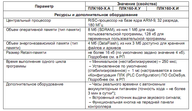
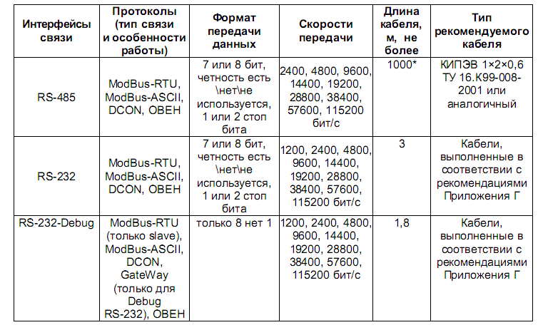
The main technical characteristics of the PLC-160 are given in the tables below.
Main characteristics of PLC-160:
Communication and programming interfaces
Description of the software
The executable program of the controller is functionally decomposed into two modules, each of which performs a certain part of the algorithm and is written in its own language. Such a division is justified by the fact that it is advisable to use special tools for various types of tasks. So, for processing input states and performing logical operations, the CFC function block language is more suitable (and more visual), which contains a large set of ready-made blocks, each of which performs a specific function. The programmer only needs to select the necessary set of blocks for the implementation of a particular program, set the specific properties of these objects and compile the source code. This approach, with certain skills, significantly speeds up the process of creating programs, since it makes it possible to use ready-made developments.
The first part of the software is made in a high-level language - ST (structured text), which is not as clear as CFC, but in contrast to this is more flexible, allows you to create compact, but complex conditions. In this program, the ST code implements the function of reading values from the temperature sensor connected to the PLC analog input and, based on them, selects the freeze timer setting. This provides weather-dependent control. The program code on ST is shown in the figure below, part of the CFC module is shown in the following figures.
The ST program is a sequence of IF selection statements, each of which controls its own temperature zone and outputs the value of the freeze timer operating time setpoint, which is written to a common register for all operators. More compact code can be obtained by using a single multiple choice CASE operator, but in Codesys 2 this operator does not support working with numbers in floating point format.
The time calculated to start the timer has a format in minutes, but for a visual (accelerated) demonstration of the work, a software correction has been introduced, in which one minute is equal to one second of real time.
ST code module
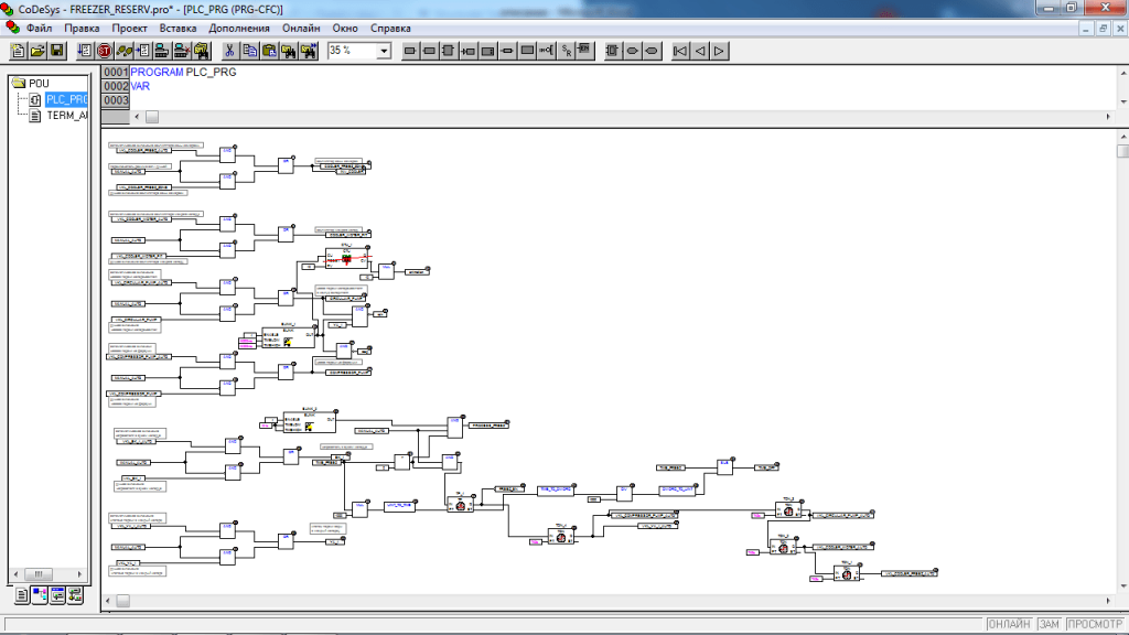
The second part of the algorithm is made in the language of function blocks - CFC. Due to the significant amount of code, a complete listing of the module program is possible only with a slight reduction in scale, so below are the figures illustrating the main branches of the algorithm.
Full listing of CFC module at 30% scale
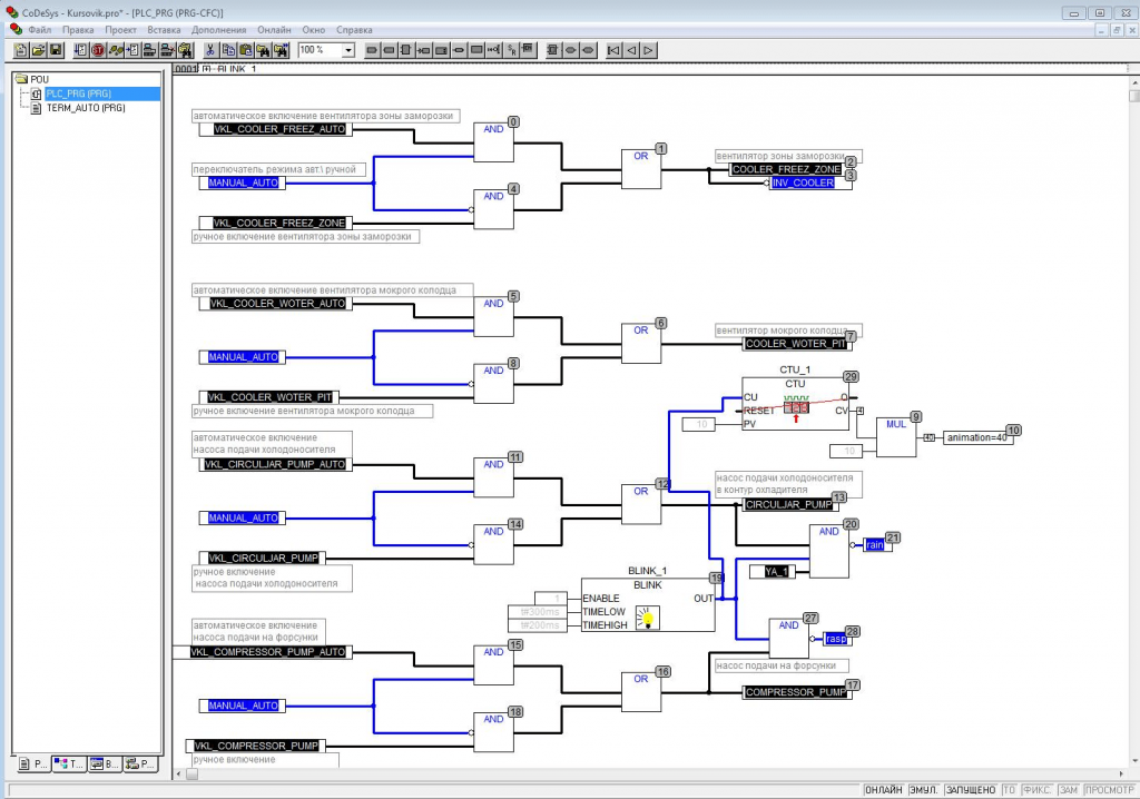
Operating mode selection modules
The physical discrete inputs of the controller (input ports) are connected through software configuration to logical assemblies on the AND and OR elements, which perform the function of switching (selecting) control signals from the buttons on the panel in manual mode, or from program control signals when the algorithm is running. Let us explain the operation of the selection module using the example of turning on the freezing zone fan, other loads are controlled in a similar way.
If the Automatic \ Manual switch is set to the Automatic position, then the log. 1 from it goes to one of the inputs of the AND elements - 0 and 4. Element 4 has an inversion compared to 0, since it has an inverse input. The second input of these elements receives a signal from manual and automatic control. Thus, the state of the inputs (1 and 1) in which it is possible to transfer control through the element will be alternately, either through the zero or through the fourth element, depending on the position of the operation type selection switch.
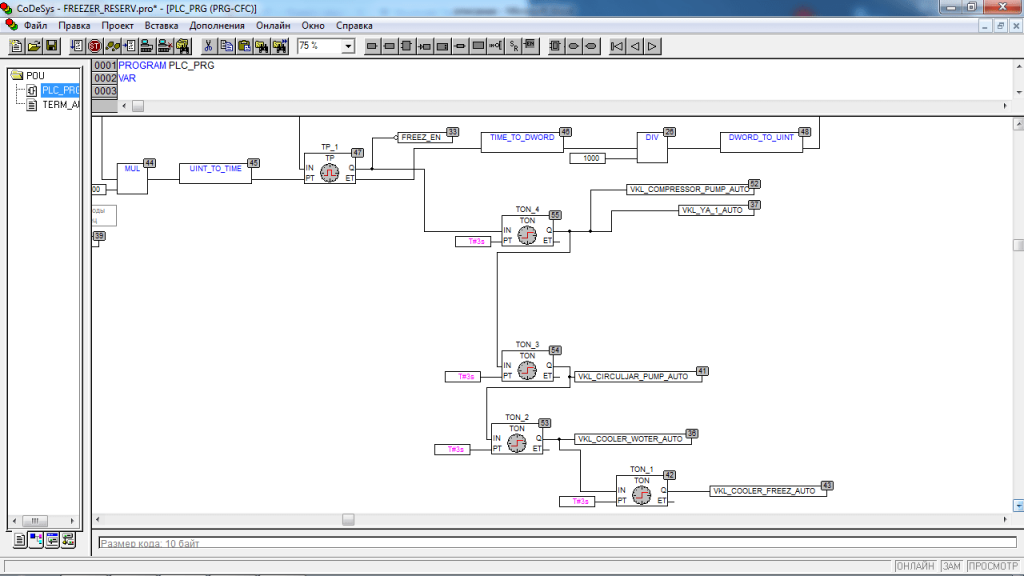
Further, the enable signal goes to element 1 - OR, which sums up the signals from the sources and passes them directly to the load control. After turning on the start in automatic mode (if it is not blocked by the conditions of the algorithm), the start sequence is switched on, implemented on timers with a turn-on delay - TON. These modules (TON_1 ... TON_4) delay the establishment of the output signal relative to the input for a specified time. In this program, the modules are used in order to prevent the simultaneous switching on of powerful consumers - asynchronous motors that have a significant starting current.
The freezing cycle itself is implemented on another type of timers - TP_1 (arbitrary time interval timer) which takes the calculated value of the freezing time from the program on ST and, when the automatic mode is turned on, produces an output pulse equal to the specified interval. On the trailing edge of the pulse, all consumers are turned off - the ice making cycle is completed.
In addition to the marked elements, the program uses other blocks that perform auxiliary functions. For example, the pulse generators BLINK_1 and BLINK_2 are necessary for “blinking” of visualization elements, and the incremental counter CTU_1 provides animation of the movement of air flows in the freezing zone. The X coordinate of the position of the flow direction arrows is tied to the current state of the counter, which causes them to move along the longitudinal axis.
A chain of sequential launch modules.
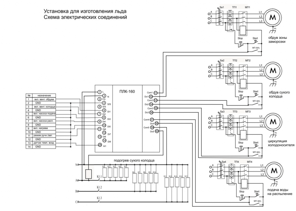
Description of the operation of the circuit diagram.
Contactor control signals are taken directly from the controller outputs, without the use of intermediate relays. However, it should be taken into account that when using starters with windings consuming more than 20W, the use of intermediate relays becomes appropriate to protect the controller's built-in relays from overloads and extend their life.
The controller receives discrete control signals from remote buttons on the wall of the control box (or from the operator panel on a PC), as well as from an analog temperature sensor, and, in accordance with the program logic, issues control actions to the outputs, controlling the operation of certain actuators.Consider the operation of the circuit using the example of a channel for switching on a fan for blowing a dry well, other loads are switched on in a similar way. When the manual mode is on and a signal is received from the blower switch (or from the button on the PC panel), the controller gives a signal to turn on, the internal relay is activated, which connects the starter coil to one of the phases with its contacts. The starter operates and supplies power to the electric. blower fan motor. In series with each starter, thermal relays are included, which are designed to turn off the electric. engines under long-term loads close to critical. The characteristic of the thermal relay must be matched to the specific rated power of the engine at idle. The dry well is heated by three groups of heating elements connected according to the “star” scheme, which ensures a uniform distribution of loads over the supply phases. The controller outputs, through which the starters are switched on, are duplicated by external, mechanically connected Start and Stop switches located on the front door of the control cabinet, which makes it possible to manually control the loads quickly (for example, when the controller breaks down and is sent for repair). When installing the control cabinet, one should take into account possible unfavorable conditions for placing equipment at the facility (low temperature, high humidity) and use structural elements with a degree of protection of at least IP 60.
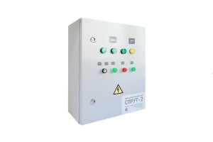
An approximate view of the control cabinet is shown in fig. 5 To protect against low temperatures, it should be possible to heat the internal space with low-power heating elements or low-power incandescent lamps.
Option for moisture-proof execution of the control cabinet.
Operator's manual
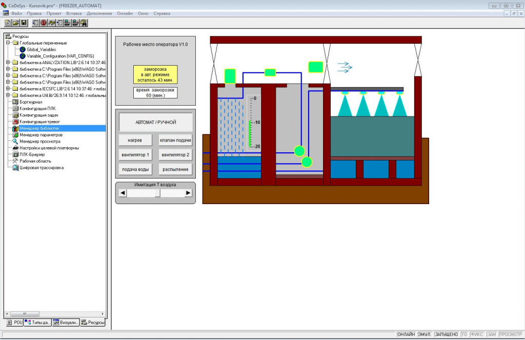
The workflow is displayed in the integrated Codesys 2 system (the controller must be connected to a PC via one of the communication interfaces). The operator's workplace is a mnemonic diagram with the functional elements of the freezing system, controls and controls located on it.
Process Control Window
After loading the workspace, you must press the F5 key to run the program. By default, the manual control mode is enabled, which makes it possible to check the functioning of certain actuators before starting the automatic mode. On the right side of the mnemonic diagram, a section of the installation is conventionally shown - dry and wet wells, an ice accumulator chamber, circulation and spray pumps, fans and communications.
On the left side are the controls for the installation in manual mode. The panel also has a setpoint controller that mimics a dry well outside temperature sensor that can be set to a desired temperature value to test program operation. In automatic mode, the freezing time is calculated by the tabular method based on the air temperature in the dry well. In manual mode, the freezing time is determined by the operator.
When the Automatic / Manual button is pressed, the algorithm of the system startup sequence is activated, then the freezing timer starts for the estimated time. The start sequence is hard-coded in the program cycle and is a series of time sequential delays, when each subsequent load is turned on after the previous one is started.
#Processlayeredfrostice, #Coursework

Be the first to comment